
Radioddity Help Center
-
![]()
Radioddity
-
![]()
Baofeng
-
![]()
Xiegu
-
![]()
TYT
-
![]()
Accessories
-
![]()
Other Tips
-
![]()
Radio Comparison


There is no key combo to blank the contents of the Active Client ID Library.
The following procedure will achieve the same goal.
Open Active Client
Hold # key Side Key 2 and Menu while turning the radio on.
Read the radio to display the contents
Open the Data Dump file from the DMR ID folder
Open a Blank Excel file
Copy the top 2 lines from the Data Dump and paste into the Blank file
Edit the first entry to seven zeros for the Radio ID, change the Callsign, Name
and Nickname to R4DIO, Test, and Entry
Save this new file in .csv format.
Close Active Client
Open Active Client
Import the .csv you just created
Close Active Client
Open Active Client
Read Radio to verify
This is a few extra steps, but will erase the entries and replace with one test
entry.
For the firmware update error, please find the vcredist_x86_2008 file in the Firmware software V3.1.8--update software document and run it first. It is a database which can help you solve the error. Please see the screenshots below:


After you run the vcredist_x86_2008 file, please restart
your computer, replug in the radio and try to update the firmware again.
If you prefer to use the vcredist_x86_2008 package in English, this is the same
module that can be downloaded from Microsoft here:
https://www.microsoft.com/en-us/download/details.aspx?id=29
--- Choose English as the language
--- Download
--- substitute this file for the file that is in Chinese
--- Run as Administrator
If your computer pops out the error "Update.exe – System Error The program can’t
start because STDFU.dll is missing from your computer. Try reinstalling the
program to fix this problem."
The file "STDFU.dll" is already included in the original download folder. The
solution is that the "Update.exe" program MUST always be in the exact same
folder as the "STDFU.dll" file and cannot be moved.
How to enter the advanced mode in the GD-77 programming software?
Press Ctrl+Alt+Shift+5, enter the password: DMR961510
or
Press Ctrl+Alt+Shift+F11, enter the password: DMR961510
Solution:
Would you mind following the operation in the link below and see if the display
problem can be fixed?
https://radioddity.s3.amazonaws.com/Radioddity - repair GD-77 white screen.pdf
If the display still shows nothing, please write back with your radio's serial
number and we will help you further.
Question:
Why in GD-77 firmware V3.1.9, the privacy key is shorter than V3.1.1?
Left: V3.1.1. Right: V3.1.9

Answer:
64 bits actually does not work on the radio, so we cancel it in the new
firmware.
Question:
Does the RADIODDITY GD-77 support NXDN digital communication?
Answer:
No
Questions:
I would like detailed information on the encryption capabilities of the
Radioddity GD-77 DMR radios please.
Answer:
Encryption protocol: ARC4
P.S.
Some customers may say they saw the GD-77 is equipped with an AES chip in some
disassembly photos. The encryption chip of GD-77's vocoder library is AES, but
for the radio encryption protocol, it only supports ARC4 for now.
If the radio is not allowing you to select bandwidth or set a tone from the
menu, it will need to have the firmware updated to remove all preset tones and
make that Menu selection active, as well as the Bandwidth options.
To update the firmware, use the following link:
https://radioddity.s3.amazonaws.com/Radioddity_GM-30_Firmware%2020210403%20%26%20Software_V2.06_20210430.zip
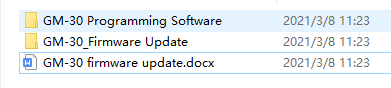
Download and Extract the files from the archive and open the GM-30 Programming
Software folder
Open the Radioddity GM-30 v1.05 en installation app.
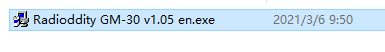
Install the Programming Software and Open App
Plug the programming cable into the computer
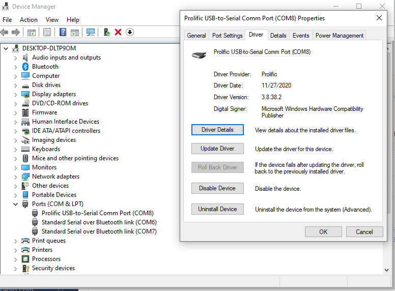
Open Device Manager to determine com port number
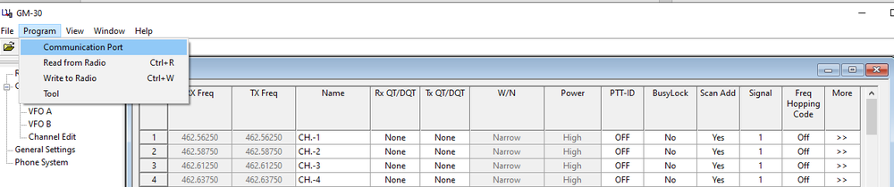
Select Communication Port from the Program Tab
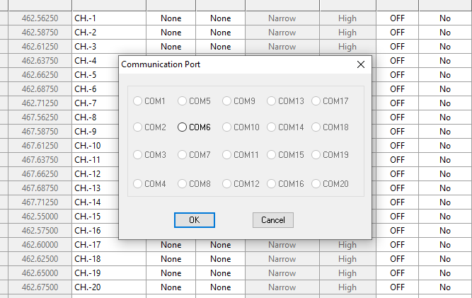
Select the appropriate port
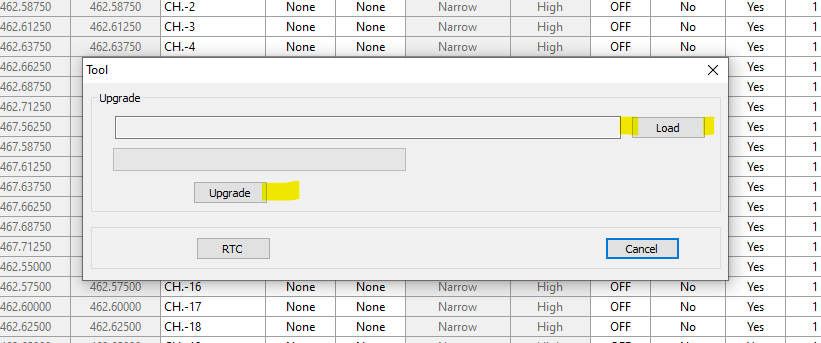
Select Program, then Tool
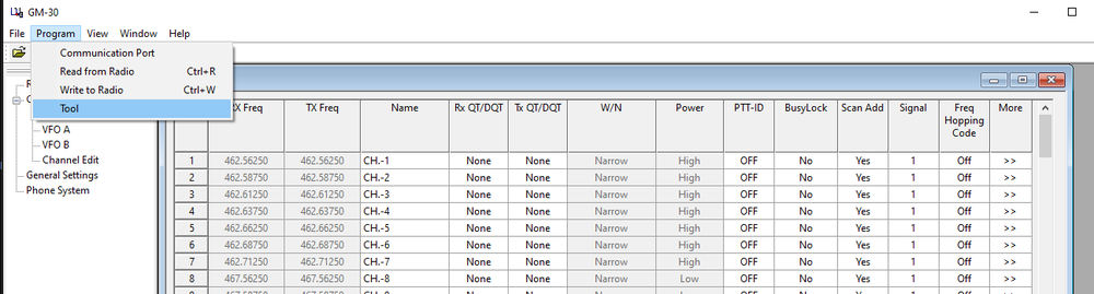

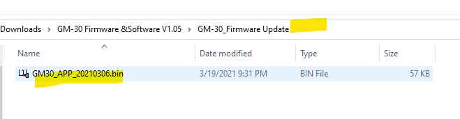
Select and Load the Upgrade file from the GM-30_Firmware Update folder
Plug the programming cable into the radio
Press and hold the PTT + LED key, then turn the radio on
Click Update - Wait for 100%
Turn the radio off, remove the programming cable
Turn the radio back on and select Menu Option 40 and follow through to Reset the
radio.
The Bandwidth settings should now be corrected and existing DTDSS/SCS tones
removed.
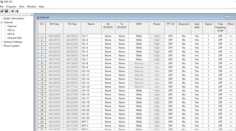
The CTCSS/DCS Tones can now be set from the programming software and written to
the radio, or by using Menu Options 9 through 12
Question:
How to active the VOX function on the GA-2S/BF-888S/BF-88A/BF-88E?
Answer:
To enable the VOX function, here are two ways:
1. Select the current channel to one of the 1-5 channels, press and hold the PTT
and Moni button to turn on the radio, then you will hear the voice prompt that
the VOX is on. In this way, all the 16 channels have been activated the VOX
function and the user can talk directly to transmit without pressing the PTT
button. With the acoustic tube earpiece, the users can hear and talk more
clearly.
2. You can activate the VOX function in the programming software. Select the VOX
function and all the 16 channels can use the VOX function directly. Normally
turn on the radio and you can use the VOX function no matter which channel you
are at.
To turn off the VOX function, turn off the radio, set the current channel to one
of the 1-5 channels, press and hold the PTT and Moni button to turn on the
radio, then you will hear the voice prompt that the VOX is off. If the VOX is
turned off, you will see the VOX function is not selected when you load the
radio to the programming software.

Question:
I was wondering if the radioddity GA-2S long range two way radio can connect
with a cp200 Motorola if same frequency and channel.
Answer:
Yes, they can communicate with each other under analog mode with correct
programming.
Question:
How to scan multiple channels on a GA-2S radio? I can't seem to get the radio to
scan like in the instruction manual. Pressing the monitor button only monitors
that current channel (and usually gives me loud static sounds).
Answer:
There is no scan function on GA-2S.
Some GD-73 users reported that they can't get the driver installed well on
Windows 10 or can't run the programming software on Windows 10. Below are two
solutions to solve the problem:
Solution #1:
Install the driver as administrator
Solution #2:
If the driver still can't be installed correctly even if the user has run it as
administrator, please suggest the user remove the original driver and then
install the driver from the following link:
https://sourceforge.net/projects/libusb-win32/files/
Users can also find the download link for this driver by searching
"libusb-win32-src-1.2.6.0.zip" on the internet. No need to install the original
driver we provide if users have installed this driver.
PROBLEM:
Customer reports that he can't run the GD-73 programming software(CPS) on his computer. An error showed up and said that file libusb0.dll is missing.
Background--why the software of GD-73 is different from other radios:
The combination of charging and programming from the same connector has introduced the need for a new driver installation and installation order to be required. For the first time running the GD-73 CPS on a computer, the user needs to install the driver first and get the radio connected with the computer.
Solution:
1. Turn on the radio and plug in the programming cable (to both radio and computer).
2. Install the driver. Most important, run the driver installer application as Administrator to install the required driver.
For more information about installing the driver, please see the following instruction:
https://radioddity.s3.amazonaws.com/2019-06-05_Radioddity_GD-73_ Getting_On-Air_V1.0.pdf
3. Open Device Manager and look for a device named libusb-win32 devices. Open it and it should have a cable icon and walkie-talkie-C7000 beside it.
4. Now, with the radio connected to the computer and verified by the device in the Device Manager, you can run the CPS.
5. After the first time running the CPS, you can open it with or without
connecting the radio on the same computer next time.
Questions:
The functions I would like to use on the GD-73E are the following:
-enter a code for the encryption
-enter a short message
-open the squelch to check if a frequency is free.
Answer:
*All these three functions can only be set on the CPS
-enter a code for the encryption:

-enter a short message:
To send short message on the radio, user needs to add quick text in the CPS
first. And this can only be done on the CPS.

-open the squelch:
Set the squelch level in the General Settings.

It is difficult to save an offset to memory when programming the QB25 without
a computer.
The following steps will allow you to save a complete channel with offsets and
any signal tones necessary.
Delete channel (if necessary) - Menu 45
Switch to VFO
Enter RX Frequency (enter zeros if needed to fill all blanks. Example 146.7000)
Enter RX Tone (if needed)
Save to empty channel - Menu 44
Enter TX Frequency (enter zeros if needed to fill all blanks. Example 146.1000)
Enter TX Tone (if needed)
Save to the same channel as RX frequency - Menu 44
(Hold the Right knob in until it returns to the operating screen)
Change to Memory, Select Channel, and check operation.
When trying to open the DB25 or QB25 CPS, you may encounter an error that a
file that is necessary for the program to run is missing.
Navigate to the folder where the application is located and right-click on the
app: DB25QB25_VIP_CPS
Select Run as Administrator - Windows should now find the file that is in
the same directory as the App and allow you to use CPS.
If the problem persists, the missing file(s) will have to be registered.
This is more likely to occur on a new computer where the Microsoft
communications support files have not all been registered.
==================================
This is How Users can Fix the MSCOMCTL.OCX is Missing Error
1.
Check the Desktop’s or Laptop’s System Details
2.
Register the MSCOMCTL.OCX File on 64-bit Systems
3.
Register the MSCOMCTL.OCX File on 32-bit Systems
4.
Reinstall the Software
Check the Desktop’s or Laptop’s System Details
1. First, users should check whether their laptops or desktops are 32 or 64-bit
systems as the directory users need to register the MSCOMCTL.OCX file for is not
the same for both. To do so, press the Windows key + S hotkey.
2. Enter the keyword ‘system information’ in the search box.
3. Click
System Information to open the window in the shot directly below.

4. Then select System Summary, and check the System Type detail there. An x64
system type is a 64-bit system.
2. Register the MSCOMCTL.OCX File on 64-bit Systems
Users with 64-bit desktops or laptops will need to register an MSCOMCTL.OCX file
for the SysWOW 64-bit folder. To do so, open
File Explorer
with the Windows key + E hotkey. Then open this folder path in File Explorer:
C:WindowsSysWOW64.

The SysWOW64 folder will need to include the MSCOMCTL.OCX file. If it doesn’t, users will need to get that MSCOMCTL file from an OCX file directory or by copying it from another PC. However, note that some website sources for OCX files might not be entirely reputable. Some users might find an MSCOMCTL.OCX file in a third-party software folder so tries searching for the file with Windows’ search utility first. When you’ve copied a valid MSCOMCTL.OCX file into the SysWOW64 folder, follow the guidelines below to register the file.
1. Press the Windows key + R hotkey.
2. Enter ‘cmd’ in Run, and press the Ctrl + Shift + Enter hotkey, which will open an elevated Command Prompt window.
3. Next, open the SysWOW64 folder by entering ‘cd C:WindowsSysWOW64’ in the Command Prompt’s window and press Return.

4. Then input ‘regsvr32 mscomctl.ocx’ in the Prompt, and press the Enter key.

3. Register the MSCOMCTL.OCX File on 32-bit Systems
Users with a 32-bit system will need to check that there’s an MSCOMCTL.OCX file in the cd C:WindowsSystem32 folder instead of SysWOW64. Copy an MSCOMCTL.OCX file into System32 if that folder doesn’t include the required file. In addition, 32-bit system users will need to enter cd C:WindowsSystem32 in an elevated Command Prompt. However, users can still register the file with the same ‘regsvr32 mscomctl.ocx’ command.
4. Reinstall the Software
Aside from registering the OCX file, users have also confirmed they’ve fixed the MSCOMCTL.OCX error by reinstalling the software that doesn’t run. That will ensure the software installs correctly. Users can reinstall the software in Windows as follows.
1. Open the Run window with the Windows key + R keyboard shortcut.
2. Input ‘appwiz.cpl’ in Run and click OK to open Windows’ uninstaller.

3. Select the software that the MSCOMCTL.OCX error arises for.
4. Select Uninstall or Uninstall/Change option.
5. Then click Yes to confirm.
6. Restart Windows before reinstalling the software.
7. Then reinstall the latest version of the software.
So, that’s how users can fix the MSCOMCTL.OCX error message in Windows to kick-start certain software. First, try reinstalling the software as that’s probably the more straightforward resolution.
There is a passive GPS antenna automatic gain control chip inside the radio. So a passive one is recommended.
Several customers have asked for more advise and details on using the CPS supplied for our DB25-D dual mode dual band mobile radio. As we care on the demand of our customers, our engineers, together with our Customer Support staff, have put together a quite comprehensive Addendum to the existing manual you got with your DB25-D. It also does include the details for using the GPS-functionality of the DB25-D together with APRS, both in analog as well as in digital mode.
CLICK HERE to get your copy of this brand new addendum.
------ by SAVO LUZAR S52SX
1. Guide how to set up APRS to Radioddity DB25-D
1.1 BASICS
1.1.1 Update radio to the latest firmware and use proper software for programming your radio.
1.1.2 Always read code plug from radio, make a change to code plug and then write it back to the radio, because in this case your code plug will have all correct data that match to your radio.
1.1.3 Never write data to the radio from different version of CPS, while this will lead to unpropped function/working of your radio.
1.1.4 That guide will work only in WINDOWS environment on your PC or Laptop.
1.2 Settings in Radio Radioddity DB25-D
You need to prepare your radio for APRS.
Press Menu, go to Appendix, Choose GPS (red icon) and you will see this menu.
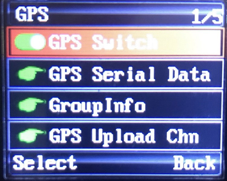
Enable GPS Switch.
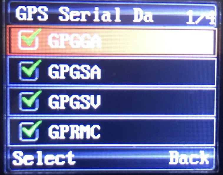
Under GPS Serial Data tick all options.
Go to Calibrator and set to AUTO.
Now go back to appendix menu and choose APRS.
In APRS Menu you have 5 options: APRS Type, Analog APRS, DMR APRS, Timer and Beacon.

Select APRS Type, you will see 4 options, select DMR+Analog APRS.
Under Analog APRS choose PTT Upload and choose TX End.
All other settings we will made in CPS.
1.3 Connect your Radio to your PC/Laptop
Connect your radio with USB cable and set proper USB Port by clicking on Comm Menu.
Choose proper COMM port and click Read, you will get response from your radio.

Always Read from the radio, do not open saved code plug.
1.4 DMR Service Menu
Go to the DMR Service and set:
GPS to ON, GPS Interval 10s, GPS Channel OFF

1.5 APRS Menu
Under the MENU APRS you have following:

1.5.1 Black frame settings:
Manual TX, set 15.
APRS Auto TX Interval set to 30s.
Under Beacon – set Beacon. Here you have two options – GPS Location or Fixed Location.
If you choose Fixed Location your radio will transmit GPS Coordinate marked in green frame!
1.5.2 Green frame settings:
You can find own coordinates by web browser or visit www.aprsdirect.com.
Be Aware that those Coordinate are in Slovenia right now.
Those are in format Latitude 46°10' 11ˇ N and Longitude 14°20'18ˇ E
1.5.3 RED frame settings:
TX frequency: for Europe Africa and Russia is 144.80, for all other counties check picture bellow.
TX QT/DTQ – this is analogue or digital tone. Leave this to OFF. If in your country is in use tone, that ask your local igate owner what kind of tone is
used to open igate.
Transmit Delay and Preware Time: Optimal setting are 500ms and 300 ms, if you think this scan be decreased, go ahead and test it.
1.5.4 BLUE frame settings:
YOUR SSID: you have options from 0 to -15, it up to you what kind of extension you would like to have. Usually 0, -1.-2 are used for fixed location, -7 for weather station, all other extension can be normally used.
APRS Signal Path: WIDE1-1, is working fine, you can also use WIDE2-1 and WIDE2-2. Always use this without any space.
You Call Sign: put in your call sign.
APRS Symbol table: there are two option according to APRS map chart – primary symbols ˇ/ ˇ and alternate symbols ˇ \ ˇ
Map Symbols can be found at this link: https://www.yachttrack.org/info_camper/downloads/APRS_Symbol_Chart.pdf
APRS Map Icon: According to the map symbols you can use whatever icon you like.
Your Sending Text: Here you can write a text, that everyone can be seen, if click on your call sing in web page www.aprs.fi or www.aprsdirect.com

1.5.5 Yellow Frame Settings:
This setting are for digital APRS via DMR repeater’s.
Report Channel You can choose Current channel, or any other channel in your channel list. I recommend to use Current channel.
APRS TG: this is assembly from country code (293 for Slovenia) and 999 for TG for Brandmeister. 293999 is for Slovenia.
Report Slot: In Europe is allowed to transmit Digital APRS only on Time Slot 2.
Call Type: Digital APRS must be set to Private call.
PTT: options are OFF and ON. If you choose ON, that every time you released PTT button radio will transmit APRS.

2.0 Digital APRS registering at Brandmeister.
For Digital APRS you must be registered to Brendmaister. Please check what type of DMR repeaters are in use in your country.
Go to the following web page: https://brandmeister.network/
Klick register and filled up all necessary data. Sometimes you need to way a while that your account be to confirmed.
After confirmation click to Login and put in your credentials.
Click on your call sign on the right upper corner and choose Selfcare.

Brand: Choose Chinese radio.
Language: Choose your language on drop down menu.
APRS interval: choose 60s.
APRS Callsign: put your callsign and extension from -1 to -15.
APRS Text: put your text in, but MAX 12 letters!
APRS Icon: choose your Icon which will be displayed on web pages like aprs.fi and aprsdirect.
In Call GPS, Compact/CSBK data and Text Capture: leave to OFF.
AirSecurity/TOTP: OFF
Hotspot Security: if you have a hotspot, then put in your personal password.
Do not forget to press SAVE button at the end.
3.0 Channel setting in your code plug for analog APRS
For test make one analog channel and name it APRS ANA.
Put correct RX and TX frequency for your country. Check picture above.

Move slider to the right and under APRS choose APRS(A) for this analog channel.

Column marked with RED - you can choose from OFF to 9 APRS(A) in drop down menu.
Row marked with Green is channel we made for test. You need to choose APRS (A).
As you can see you can choose analog APRS(A) on any channel!
WARNING: analog APRS will work only on analog channels!
4.0 Channels settings in code plug for Digital APRS
NOTE: in Europe digital APRS is allowed to transmit only on TS2!

On your digital channel, set everything as normal talk channel, TX, RX frequency, Power, TX, RX Time Slot, TX, RX Colour Code… etc.

At the end of the row, on the right side, under the APRS column for TS 1 choose 2, and for TS2 choose 1 - that mean current channel.

Under APRS Menu you need to choose Report Channel, filled in proper APRS TG, you need to choose TS2, Private CALL and under PTT is option, when you released PTT button APRS will be sent.
Now press button WRITE that everything will be written to your radio and wait that radio reboot itself.
5.0 How to obtain GPS Lock on your radio
5.1 Option 1
You need to be in open spare/area and have visible look to sky. Turn on radio and wait that radio lock to the GPS satellites When Radio locked to the satellite you will observe green icon in the upper centre of the screen. If there is NO GPS lock icon is RED.

5.2 Option 2
You can buy a kit of two GPS antennas with SMA connector and connector for external power supply. One is receiver (install it outdoor) and second antenna is transmitter (install it indoor), connect external power supply and you have GPS signal in your room.

6.0 DISLACIMER
I’m NOT TAKING ANY RESPONCIBILLITY for any sort of damage or any sort of interferences you may make with your radio equipment.
Everything you do, you do it on your own risk, don’t blame me, if there will be some damage or not working. Read manuals again!
If you not familiar with DMR please take your time and search on web or ask any of your colleague what DMR is and how it works.
If you not know how to program your radio, then ask any of your friend how to do it.
WARNING: Firmware is not finish yet so Digital APRS will transmit and proper work only on TS2
DO NOT CHOOSE Digital APRS to work on TS1, because IT WILL NOT WORK and you will make an unnecessary traffic on TS1!
NOTE2: Digital APRS will work only on digital channels!
That guide is completely my project and its only lead you how to set up your radio to send Analog and Digital APRS.
We are working very hard to fix firmware in the near future that all function will be operational
It's AES 128 standard.
The Link Below will provide the firmware update application and new firmware,
as well as the latest Programming Software build.
https://baofeng.s3.amazonaws.com/Baofeng_UV-5X_Firmware_V1.9_CPS_V2.0_Update_20210309.zip
Download, Extract and Open the UV-5X Firmware Update Folder

Open the BF_Download APP


Open Device Manager to determine com port number and select it using the
highlighted field in the Downloader App

1. Plug the programming cable into the computer and radio.
2. Press and hold the MONI + CALL key, then turn the radio on. The screen should
show a wide block in the middle
3. Click Download in the Downloader app, and wait for 100%.
4. Turn the radio off, remove the programming cable
5. Turn the radio back on and select Menu Option 40 and follow through to Reset
the radio.
The CTCSS/DCS Tones should now be cleared and the Bandwidth corrected.
Hi ,
The Link Below will provide the firmware update application and new firmware, as
well as the latest Programming Software build.
https://baofeng.s3.amazonaws.com/Baofeng_UV-5X_Firmware_V1.9_CPS_V2.0_Update_20210309.zip
Download, Extract and Open the UV-5X Firmware Update Folder


Open Device Manager to determine com port number and select it using the
highlighted field in the Downloader App

1. Plug the programming cable into the computer and radio.
2. Press and hold the MONI + CALL key, then turn the radio on. The screen should
show a wide block in the middle
3. Click Download in the Downloader app, and wait for 100%.
4. Turn the radio off, remove the programming cable
5. Turn the radio back on and select Menu Option 40 and follow through to Reset
the radio.
The CTCSS/DCS Tones should now be cleared and the Bandwidth corrected.
The radio is set to a tone of 67 Hz by default, in the first 7 channels. It
has a DCS tone number D023N set on channels 8 through 14. The repeater pairs on
channels 23 through 30 use a CTCSS Tone of 136.5 Hz.
All channels have either CTCSS or DCS tones set and will have to be edited with
the programming software, or the information shares with others needing to
communicate with you. If the other radios do not transit a matching tone, you
will not hear them.
https://radioddity.s3.amazonaws.com/Baofeng%20UV-5X%EF%BC%88GMRS%EF%BC%89Programming%20Software_20210220.rar
The easiest workaround is to press and hold the Monitor button (below the PTT)
when you see a transmission coming in, but the speaker is not unmuted.
By default, all channels are selected in the Scan Add column. The NOAA channels can be set to OFF, and will not stop the scan operation.
GMRS does require a license in the U.S., but not in Canada.
In Canada, hand-held GMRS radios up to 2 watts have been approved for use
without a license since September 2004. Typically these are dual FRS and GMRS
units, with fixed antennas, and operating at 2 watts on some GMRS channels and
0.5 watts on the FRS-only channels.
If your DM-1701 radio suddently required a power-on password while he did not
(remember) try to set any password for the radio, try the following solution.
Solution:
The instructions below should assist you in removing the password.
If the default password set by the Programming Software (CPS) ""00000000"" does
not work, the situation can be reversed, but it is going to take a few steps.

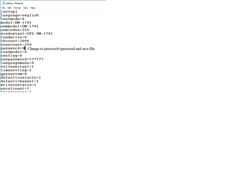
1). Using Windows File Manager, open the folder that the DM-1701 CPS is started
from. The default location is C:\BAOFENG\CPS DM-1701 V1.0x, where x is the last
digit of the Version. Located in this directory, you will find a file named
""setting"".
2). Open this file using Notepad (Right-Click on the File and Choose Open With,
then Choose Notepad from the Application choices offered) .
3). Locate the Line that has ""password=0"". Change this to
""password=password"" & save the change. Save the edited file using the Save
option, not the Save As option [See screen capture attached for setting file
contents].
4). Then open the CPS (If already opened before editing the setting file, close
the CPS and open it again for the CPS to recognize the change in the setting
file) .
5). Write a Blank data file (codeplug) to the radio. This is generated with the
New option from the File menu of the program software. It will contain the
change in the setting file.
6). Once that is done, choose Read from the Program tab in the CPS to retrieve
the modified codeplug.
7). Edit the data for the correct values - Password(s), Radio Name, etc. Items
to pay attention to will be the Password and Lock in the Menu Item options &
Power On Password in the General Setting options.
8). Write the corrected codeplug to the radio.
Preparation:
GSOC does not have a built-in Bluetooth adapter, thus users need to prepare a
USB Bluetooth adapter first. The recommended model is CSR8510 A10.
GSOC Settings:
Plug the USB Bluetooth adapter to any USB port of GSOC.
Click the connecting icon showing on the screen (the icon content is OFF
LINE/G90 ONLINE/CAT ONLINE ) to pop up Bluetooth setting interface.

1. Turn on Bluetooth
2. Click SCAN to find the Bluetooth device list.
3. Click Connect/Disconnect button in the device list to
connect/disconnect.
Note: For the first time connection, you need to allow the connection on
you PC.
PC Setting:
Operating system Windows 10 x64, PC is with built-in Bluetooth.
1. Settings ->Bluetooth & other devices -> Turn on Bluetooth function

2. Settings ->Bluetooth & other devices -> More Bluetooth options

Check:
✔ Allow Bluetooth devices to find this PC
✔Alert me when a new Bluetooth device wants to connect
3. Click COM Ports

The GSOC BT ‘Serial Port’ is the correct port (COM8 in the image above).
Connecting Software:
At present Ham Radio Deluxe does not support Bluetooth port, we recommend you use flrig
1. Software Settings & Ports
Config->Setup->Transceiver

1.1 Set the data as the image above.
1.2 Click Init button to finish the Bluetooth connection.
Note: Due to uncertain factors such as the delay
of the Bluetooth serial port, signal-to-noise ratio and other uncertain factors,
occasionally unsuccessful situations may occur during the connection. At this
time, just click the Init button to try again. If the error is still reported,
please try closing flrig and repeat the above process
2. Connecting Interface

We are very sorry to hear that the knob of your GSOC dropped off. However, that can easily be fixed by yourself. Gently squeeze the rubber ring surrounding the actual knob on its outer side and peel off that rubber ring. Be careful not to destroy it by using any sharp tools. You should be able to get it off just with your fingers You now see a hole underneath. Now with the rubber ring still off, reseat the knob on its corresponding axis. With a 2.5mm type Allen wrench and a few turns with a gentle push (just enough so that it does not fall off again), you should be able to refix that knob to its axis. Finally, reapply the rubber belt to the knob with its flat profile facing towards the knob and its teeth profile facing to the outside.
The GSOC is more pronounced, the G90 just indicates 100%on the standard
Display unit when the radio is keyed in SSB I believe it is more of an
understanding of how the ALC works on the G90 than a problem in the radio. You
can check for yourself. Install the display unit and set your G90 to SSB, key
the mic, and look below the SWR bargraph. Instead of seeing the Bargraph on the
GSOC go all the way to the right, the G90 head simply shows 100%.
In both cases, the ALC is displayed exactly the opposite of how our conventional
radios work. The G90 needs an ALC of 95% to 100% as demonstrated by speaking
into the mic at various mic gain levels. The hotter the audio, the less ALC.
RF Gain is another thing that takes some time to adjust to. The best signal to
noise ranges are below 50% RF Gain; typically between 10% and 25%
Question:
Does the G1M radio suppot AM, SSB, CW, QRP?
Is the transmission power 2W in AM mode and 4W in SSB mode?
Answer:
The QRP is not a mode. Radios with a transmit power of less than 5W is called
QRP. The G1M can work in USD, LSB, CW and AM modes.
CW is generally used to send Morse code (telegram). SBB is divided into upper
and lower sidebands which are LSB and USB.
The transmission power of the G1M is 5W. Due to the difference in frequency
bands, it will be higher or lower than 5W in some frequency bands. This is
normal, and the power is regardless of the AM / SSB mode.
First of all, make sure you've got the latest firmware from Radioddity/Xiegu. CLICK HERE to download it.
It is possible that the firmware needs to be reloaded. This is most often seen when the radio is connected to a computer and turned on. I am including the firmware file
Open the link below, download and install the Teraterm terminal program v4.96
https://osdn.net/projects/ttssh2/releases/

Plug the USB Cable into the computer and open Device Manager. Click on the Com port, observe port number and set Port speed to 19200 BPS
Leave radio turned off

Open TeraTerm

Choose Setup, then Serial port

Verify com port number and confirm port speed is 115200 BPS

Hold the Space Bar and turn the radio on
Choose 1 to Update FW
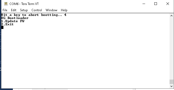
Old FW is erased

When the FW is erased, You will be prompted for the new FW file
Choose File, Transfer, Send

Highlight the FW file, and put a checkmark in the Option for 1K. It will not load properly if this is not checked

Firmware transfer is started

On completion, you will be prompted to reboot your rig

Turn Radio off
REMOVE POWER CORD FROM RADIO AND COUNT TO 10
PLUG POWER CORD BACK IN
Turn on the Radio and the operation should be restored.
WIFI Operation Instructions

SCAN: Scan for nearby Wi-Fi / hotspots (Access Point)
CONNECT/DISCONNECT: Connect/disconnect the hotspot in the left list.
EDIT: Edit the element selected by the orange box on the right.
CONFIG: Move the orange box to the next.
EXIT: Exit the interface.
1. SYSTEM SETTING – WLAN – press MFK knob to enter the Wi-Fi setting interface
 ➟
➟
 ➟
➟

2. Select a Wi-Fi to connect by rotating
MFK – press CONFIG
➟

3. Press CONFIG to move to
password – press EDIT to pop up
the digital keyboard
➟

4. Enter/delete password by rotating & press MFK knob
5. Click ENTER by rotating & press MFK knob to confirm password (important)

6. Press EDIT to exit the digital keyboard
7. Press CONNECT, please wait for about 10s

8. WiFi connected!

9. Press EXIT to exit the Wi-Fi interface

10. Wi-Fi connected confirmed!

--- --- --- --- --- --- --- --- --- ---
Bluetooth Operation Instructions

OFF/ON: Turn on/off the built-in Bluetooth function.
CONNECT/DISCONNECT: Connect/disconnect the selected Bluetooth device on
the left.
EXIT: Exit the interface.
Note: When the built-in Bluetooth function is displayed as "ON", it will
always scan the surrounding Bluetooth devices.
1. SYSTEM SETTING –
BLUETOOTH – press
MFK knob to enter the Bluetooth
setting interface
(for the first time, it should take about 1 minute to scan Bluetooth device,
please be patient; will be 5s only from second time.)
➟
 ➟
➟
2. Select a Bluetooth device by rotating
MFK – press
CONNECT to connect
(please make sure your Bluetooth device is on)
➟
3. Bluetooth connected!

4. Press EXIT to exit the Bluetooth interface
The center pin is positive. As for the included power cable, the white one is positive and black is negative.
CAT control via a USB-C cable.
It doesn't come with a touch screen, but a color screen.
A codeplug is the programming data of your radio, you can get it from the
programming software following the steps below:
1. Open the software, connect your radio to the software and read(download) from
the radio
2. Click the first button ''Open/File'' on the top line, save and then the
software will let you save the programming data and settings as a file. That
file is the codeplug.
For all customers of Radioddity we do offer all kinds of information and
software free of charge. Just get on our website
www.radioddity.com

In the upper right click on "Support".

Next select the brand of your radio (Radioddity, BAOFENG, TYT. XIEGU, OTHERS)
You will then be presented with a list of radios and accessories (of the
selected brand) that we do offer additional materials for, such as manuals
(often in other languages as well), CPS software, software for updating the
radio, firmware and other kind of special material.
Based on our customers questions and the feedback we got, our
engineers created a very detailed document targeted at beginners with digital
DMR-radios. The document takes your hand and accompanies you from the
application of your personal DMR ID up to the creation of the required codeplug.
Sample codeplugs for our DMR-radios are included as well.
What can you learn from this document?
1. Intention of this document
2. Make yourself familiar with DMR
3. Apply for and receive your DMR ID
4. Gather information about a DMR station
5. Install any USB-driver that might be required
6. Install CPS according to your DMR-capable radio
7. General process of creating a DMR code plug from scratch
8. Sample codeplugs
Download your personal copy at:
CLICK HERE to download the "Radioddity - Getting On Air With Your DMR Radio"
CLICK HERE to download the "Sample Codeplugs" (GD-77, RD-5R, DM-1701, GD-73,
MD-9600)
CTCSS: Continuous Tone Controlled Squelch System
DCS: Digitally Controlled Squelch
Cobra calls both of these features "Privacy Codes".
Privacy Codes are not extra channels -- rather they are a means for sharing a
channel with other people without any annoying interference or cross talk. Even
though there may be other people using the channel, you will only hear
transmissions from those people who are using the same Privacy Code as you.